3-Joint Robotic Arm with Claw
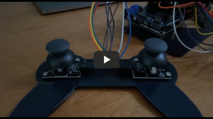
My project is a robotic arm that can pivot at three different points, and it has a claw that can grab things. The arm is controlled by two joysticks which are connected to the Arduino in the base of the arm, which then sends information to the servos that cause the arm to move.
| Engineer | School | Area of Interest | Grade |
|---|---|---|---|
| Matthew Gallop | Chatham High School | Applied Physics | Incoming Senior |

Final Milestone
My third and final milestone was programming the Arduino so I could control the servos on the arm with two joysticks. The kit for the arm came with some code, and although it was good for testing the servos and making sure everything was connected, it just didn’t move how I wanted it to. However, I wrote the code in the first milestone for this very purpose, but there was one problem, the kit had me connect the Arduino to a V5.0 extension board. This means I had to figure out how this board works and how it connects to the original Arduino. With the help of the internet, I was able to do it, though, so I rewrote some parts of my code to work with the new board. After this, it was a matter of adjusting the small things, whether I thought the arm moved too fast left to right, or I wanted the claw to close faster.
Second Milestone
For my second milestone, I built the arm of the robot with the Arduino and the servos installed. I found the instructions for my kit online and then located all the pieces I needed. The build started with creating the base of the arm with the Arduino inside and the first servo acting as the joint that allows the arm to turn left and right. I then built the main section of the arm and the next two joints; the joints were created using two servos that allow the arm to bend vertically at two different points. The final part of the arm was the claw, and it was a little more complicated as it used gears and a servo so the claw could pinch together, but I eventually got it to work. Creating the arm was actually pretty easy as I just had to follow the schematics. However, it did take me longer than I anticipated because some of the images on the instructions were hard to understand. I also couldn’t find a few pieces, so I had to improvise with some parts of the build.
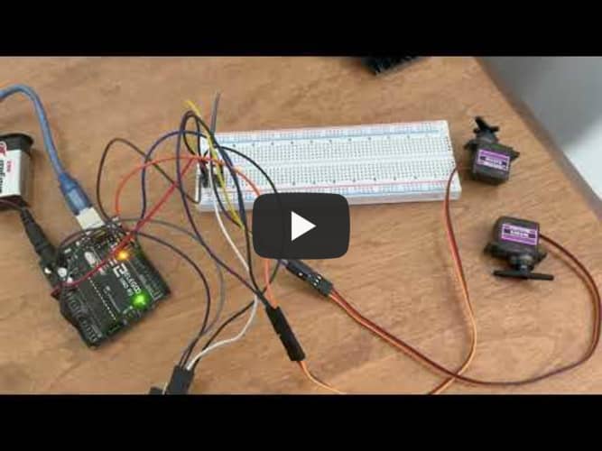
My first milestone was setting up the servos in my kit to an Arduino and then controlling them. First, I had to download the Arduino software to my computer, plug in my Arduino, and then connect the correct ports on my Arduino to the servo (ground, 5V, and a digital pin). I then had to figure out how to get the servo to move, so I used the internet to find out how to write some very basic code. When I got the servo to move, I noticed I could only turn it off by unplugging it from my computer, so I quickly realized my next step was figuring out how to use a button to turn it on and off. This part took me a while, and I had to go through a lot of trial and error to get it to work the way I wanted it to. After I got the button to work, I quickly moved on to control the servo with a joystick; I used two analog pins on my Arduino to map one servo to the x-axis and another servo to the y-axis. I then wrote some code for the Arduino to detect whenever the joystick went past a certain range, and if it did, it would send a signal to one of the servos to move. At first, the code I wrote was very clunky, and I wasn’t able to move the servos how I wanted; however, by changing the amount the servo moved and the time in between the rotations, I was able to fix this.

Reflection
Looking back on this project, I definitely learned a lot of useful skills: figuring out alternative ways to solve a problem, using the internet as a resource, and not taking shortcuts when it comes to building. However, the most valuable thing I learned in my time at Bluestamp is how almost everything in the engineering world is connected, and the more you broaden your knowledge, the more successful you will be.


